
The vibration pickup senses the velocity of the vibration and converts it into an electrical signal. The analyzer receives this signal, converting it to the corresponding amplitude and frequency.
The amplitude is measured in terms of peak-to-peak displacement in mils (1 mil = .001") and is indicated on the amplitude meter.
Some instruments are equipped with a frequency meter which gives a direct readout of the predominant frequency of the vibration. Other instruments have tunable filters which allow scanning the frequency scale and reading amplitude at any particular frequency, all others being filtered out.
A strob light is used to determine the phase of vibration. It can be made to flash at the frequency of the vibration present or at any arbitrary frequency set on an internal oscillator.
A reference mark on a rotating part viewed under the strob light flashing at the vibration frequency may appear as a single frozen (or rotat-ing) mark, or as several frozen (or rotating) marks. The number of marks viewed is useful in determining the source of the vibration. The location of the mark or marks is used in balancing rotating parts.
The first step in vibration analysis is to determine the severity of the vibration, then, if the vibration is serious, a complete set of vibration readings should be taken before attempting to analyze the cause. Fig. 1 is the typical guide for end suction stock pumps as published by the Hydraulic Institute. The amplitudes shown are the overall RMS obtained without filtering to specific frequencies. Amplitudes at specific frequencies, such as vane pass frequency with multi-vane impellers, should be less than 75% of the unfiltered amplitudes allowed in Fig. 1 at the operating RPM. For other pumps, refer to Hydraulic Institute standards or pump manufacturer.
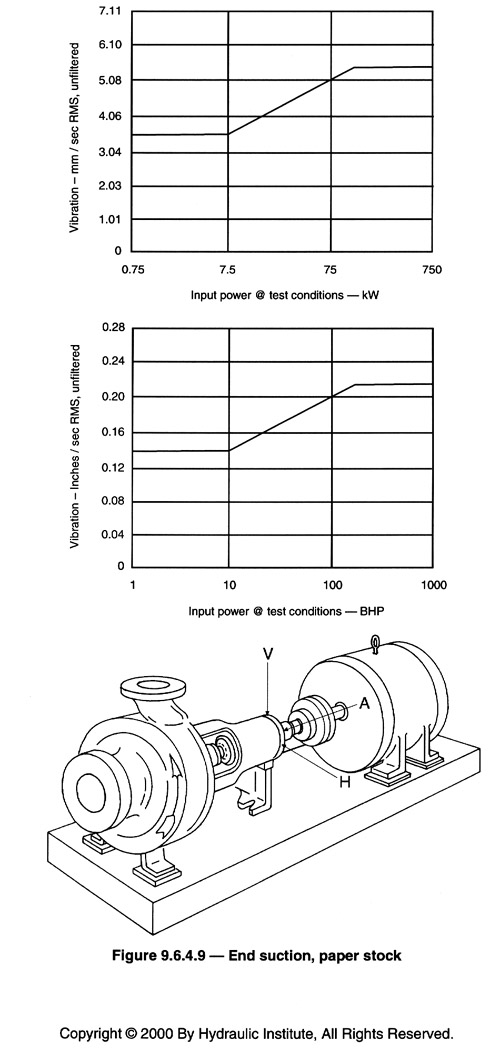
Fig. 1 Acceptable Field Vibration Limits for Horizontal Pumps - Clear Liquid (Rigid Structures)
Complete pump vibration analysis requires taking vibration readings at each bearing in three planes (horizontal, vertical and axial). Readings at the pump suction and discharge flanges may also be useful in some cases.